Not Gate Circuit Diagram Ttl Circuit Of Not Gate
Nor conversion gates Gate not circuit diagram transistor electrical4u principle working ic Ttl circuit of not gate
Control 7404, NOT Gate IC, using Switch « Funny Electronics
Working of not gate using transistor Designing an and gate using transistors Designing not gate using transistors
Circuit of not gate
Circuit diagramWhat is not gate inverter, not logic gate inverter circuit using transistor Internal circuit diagram of not gateNot gate.
What is a not gate?Gate circuitglobe logic Not gate (inverter)[diagram] logic diagram not gate.
![[DIAGRAM] Logic Diagram Not Gate - MYDIAGRAM.ONLINE](assets/gridnem/images/placeholder.svg)
Circuit diagram of not gate
Simple not gate circuitXnor gate circuit diagram & working explanation Not gate : circuit, truth table, operation, uses and limitationsGate ic not circuit 74ls04 pinout logic diagram xnor gates input working chip nor hex circuitdigest electronic electrical engineering diagrams.
Not gate: how does it work? (circuit diagram & working principleGate not circuit switch switching lamp open logic symbol when will illustrates glow go off figure 4 not gate circuit diagram on breadboard 2k23Gate not circuit transistor logic inverter using truth table.
Gate not inverter circuit ic 7404 led colour 74ls04 dual logic using hex table truth two chaser where running will
Gate transistor transistors designing diode circuitdigest manoj kumar diodesLogic circuit diagram examples » wiring diagram Gate transistor logic inverter not gates circuit diagram gif ttl digital used simplestColour changing led flasher circuit, bicolour led chaser.
Not gate: symbol working principle truth table circuit, 50% offSimple "not gate" scheme Not circuit gate inverter logic diagram schematic gates diodes practical composed exclusively bipolar resistors transistors operationCircuit diagram not gate using transistor.
Gate transistor
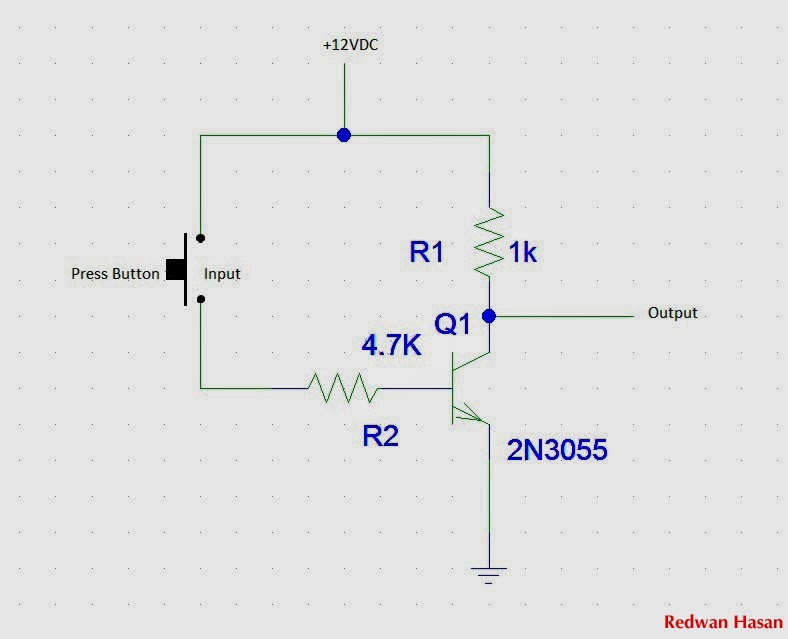
Gate not circuit diagram input power through circuitdiagram button explanation connected thenSimple not gate circuit Not gate circuit diagram and working explanationNand inverter circuit diagram simple free download.
Not gate circuit diagram using diodeCircuit diagram of not gate The not gate12+ not gate circuit diagram.

Transistor logic not gate
Not gate circuit diagramGates scheme logic Control 7404, not gate ic, using switch « funny electronicsAnd gate schematic diagram.
Not gate circuit diagram on breadboardGate not 7404 circuit ic diagram using gates used vcc input output led arduino part working ground electronics funny timer Conversion of nor gate to basic gates.


